# Freefly Systems RTK GPS
The Freefly Systems RTK GPS Module is a multiband RTK GPS module from Freefly Systems that provides highly reliable navigation. The modules can act as either rovers (when installed on an aircraft) or base stations (when plugged into a computer).
Main features include:
- Multiband (L1/L2) receiver (Ublox ZED-F9P)
- Concurrent reception of all 4 GNSS (GPS, Galileo, GLONASS, BeiDou)
- Built-in magnetometer (IST8310), baro (BMP388), RGB LED, safety switch and safety LED
Note This module can be used with PX4 v1.9 or above (support for the UBlox ZED-F9P was added in PX4 v1.9).
# Purchase
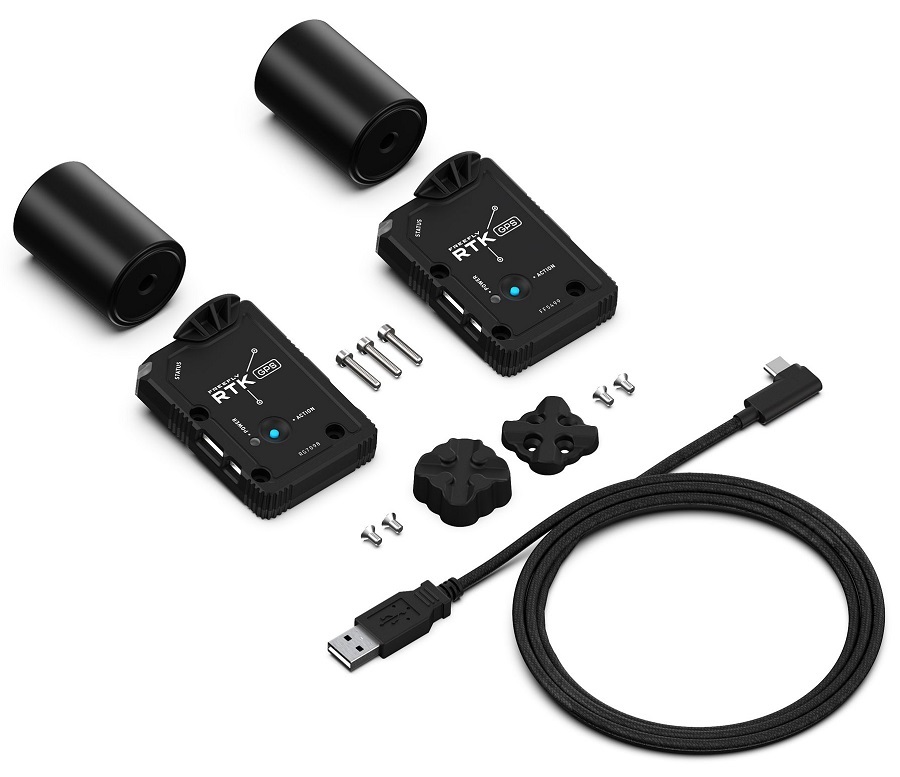
# Kit Contents
An RTK GPS kit includes:
- 2x GPS modules with antennas
- 3m USB C to A cable
- Magnetic quick-mount for base station module (1/4-20 thread for tripod mounting)
- Screws to mount onto a Freefly AltaX
# Configuration
RTK setup and use on PX4 via QGroundControl is largely plug and play (see RTK GPS for more information).
For the aircraft, you should set the parameter SER_GPS1_BAUD to 115200 8N1 to ensure that PX4 configures the correct baudrate.
# Wiring and Connections
The Freefly RTK GPS comes with an 8 pin JST-GH connector that can be plugged into a PixHawk autopilot. For use as a base station, the module has a USB-C connector
# Pinout
The Freefly GPS pinout is provided below. For some autopilots, like the Hex Cube and PixRacer, all that is needed is a 1-1 8-pin JST-GH cable.
| Pin | Freefly GPS |
|---|---|
| 1 | VCC_5V |
| 2 | GPS_RX |
| 3 | GPS_TX |
| 4 | I2C_SCL |
| 5 | I2C_SDA |
| 6 | BUTTON |
| 7 | BUTTON_LED |
| 8 | GND |
# Specification
- Ublox ZED-F9P GPS Receiver
- Ultracap backup power for fast (hot-start) restarts
- EMI shield over receiver for improved EMI immunity
- IST8310 Magnetometer
- Safety-switch and safety LED
- RGB LEDs for status indication
- NCP5623CMUTBG I2C Driver
- BMP388 Baro on I2C bus
- External, active antenna (Maxtena M7HCT)
- SMA connector
- STM32 MCU for future CAN-based communication
- FW updates through USB connector
- Connectivity:
- USB-C
- 2-way USB Switch to MCU and F9P
- SMA for active antenna (20mA max)
- 4-pin JST-GH CAN Bus (dronecode compliant)
- 8-pin JST-GH UART/I2C -** Power:
- Input from either (diode OR'd):
- USB (5V)
- CAN (4.7 to 25.2V)
- (4.7 to 25.2V)
- Power consumption <1W
# More Information
More information can be found on Freefly's Wiki