# 基本概念
本主题提供了无人机和使用 PX4 的基本介绍(主要面向新手用户,但对有经验的用户也是一个很好的介绍)。
如果你已经熟悉了基本概念,你可以转到 基本组装 以了解如何连接特定的自驾仪硬件。 要加载固件并使用 QGC 地面站 设置飞行器,请查看 基本配置。
# 无人机是什么?
无人机是无人驾驶的“机器人”设备,可以远程或自动控制。
无人机可被用于 消费级、工业级、政府、军工应用。 这包括(非详尽):航空摄影/录像,载货,竞速,搜索和测绘等。
Tip 存在用于空中、地面、海洋和水下各种不同类型的无人机。 这些(更正式地)被称为无人驾驶飞行器(UAV),无人驾驶飞行器系统(UAS),无人驾驶地面车辆(UGV),无人驾驶水面船只(USV),无人驾驶水下潜航器(UUV)。
无人机的“大脑”被称为自动驾驶仪。 它由在 载具控制器(“飞行控制器”)硬件上运行的 飞行栈 软件组成。
# PX4 自动驾驶仪 {#autopilot}
PX4 是强大的开源自动驾驶仪 飞行栈。
PX4 的一些主要功能包括:
- 可控制许多不同的设备机架/类型,包括:飞机(多旋翼,固定翼和垂直起降),地面车辆和水下潜航器。
- 适用于设备控制器,传感器和其他外围设备的硬件选择。
- 灵活而强大的飞行模式和安全功能。
PX4 是一个大型无人机平台的核心部分,它们都包括 QGC 地面站,Pixhawk 硬件,还有MAVSDK 用于与机载计算机集成,相机还有其他使用 MAVLink 协议的硬件。 PX4 由 Dronecode 项目 支持。
# QGC 地面站 {#qgc}
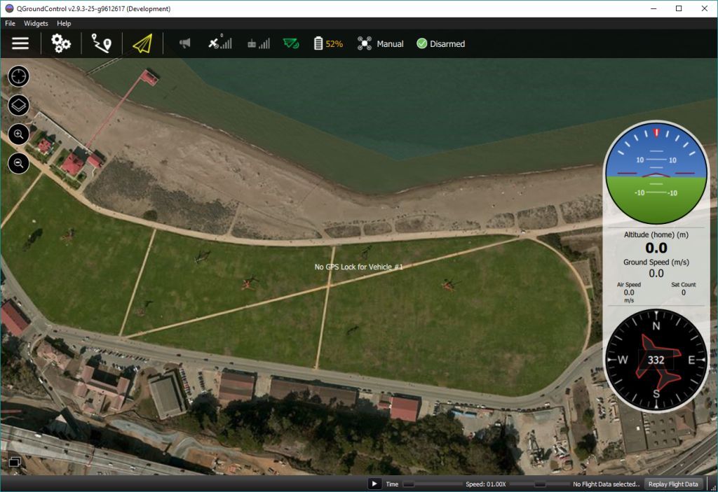
Dronecode 地面控制站称为 QGC 地面站。 您可以使用* QGroundControl *将(闪存)PX4 加载到飞行器控制硬件上,您可以设置飞行器,更改不同参数,获取实时飞行信息以及创建和执行完全自主的任务。
QGroundControl 可以在 Windows,Android,MacOS 或 Linux 上运行。 从 这里 下载并安装。
# 机体/飞行控制板 {#vehicle_controller}
PX4最初设计为在 Pixhawk 系列 飞控上运行,但现在可以在 Linux 计算机和其他硬件上运行。 选择飞行控制板时,您应当考虑飞行器的物理尺寸限制,想要执行的活动,还有必不可少的成本。
更多信息,请参阅:飞行控制器选择。
# 传感器
PX4 使用传感器来确定飞行器状态(稳定和启用自动控制所需)。 系统*最低要求 *陀螺仪,加速度计,磁力计(罗盘)和气压计。 需要 GPS 或其他定位系统来启用所有自动模式和一些辅助模式。 固定翼和 VTOL 飞行器还应包括空速传感器(强烈推荐)。
有关详细信息,请参阅︰
# Outputs: Motors, Servos, Actuators {#outputs}
PX4 uses outputs to control: motor speed (e.g. via ESC), flight surfaces like ailerons and flaps, camera triggers, parachutes, grippers, and many other types of payloads.
For example, the images below show the PWM output ports for Pixhawk 4 and Pixhawk 4 mini.
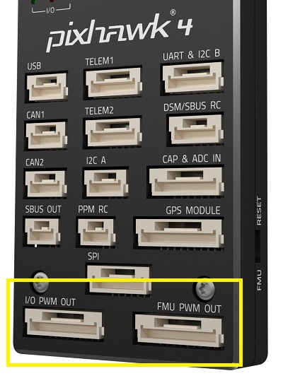
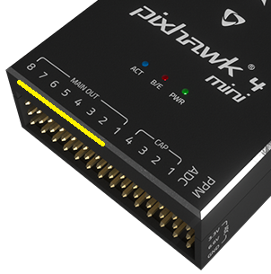
The outputs are divided into MAIN and AUX outputs, and individually numbered (i.e. MAINn and AUXn, where n is 1 to usually 6 or 8).
Tip The specific purpose for each output is hard coded on a per-airframe basis. The output mapping for all airframes is given in the Airframe Reference.
Warning A flight controller may only have
MAINoutputs (like the Pixhawk 4 Mini), or may have only 6 outputs on eitherMAINorAUX. Ensure that you select a controller that has enough of the right types of ports/outputs for your airframe.
Typically the MAIN port is used for core flight controls while AUX is used for non-critical actuators/payloads (though AUX may be used for flight controls if there aren't enough MAIN ports for the vehicle type- e.g. VTOL). For example, in a Generic Quadcopter the MAIN outputs 1-4 are used for corresponding motors, while the remaining MAIN and some AUX outputs are used for RC passthrough.
The actual ports/bus used for the outputs on the flight controller depends on the hardware and PX4 configuration. Usually the ports are mapped to PWM outputs as shown above, which are commonly screen printed MAIN OUT and AUX OUT.
They might also be marked as FMU PWM OUT or IO PWM Out (or similar). Pixhawk controllers have a "main" FMU board and may have a separate IO board. If there is an IO board, the AUX ports are connected directly to the FMU and the MAIN ports are connected to the IO board. Otherwise the MAIN ports are connected to the FMU, and there are no AUX ports. The FMU output ports can use D-shot or One-shot protocols (as well as PWM), which provide much lower-latency behaviour. This can be useful for racers and other airframes that require better performance.
The output ports may also be mapped to UAVCAN nodes (e.g. UAVCAN motor controllers). The (same) airframe mapping of outputs to nodes is used in this case.
Notes:
- There are only 6-8 outputs in
MAINandAUXbecause most flight controllers only have this many PWM/Dshot/Oneshot outputs. In theory there can be many more outputs if the bus supports it (i.e. a UAVCAN bus is not limited to this few nodes).
# ESCs & Motors {#esc_and_motors}
Many PX4 drones use brushless motors that are driven by the flight controller via an Electronic Speed Controller (ESC) (the ESC converts a signal from the flight controller to an appropriate level of power delivered to the motor).
For information about what ESC/Motors are supported by PX4 see:
- ESC & Motors
- ESC Calibration
- ESC Firmware and Protocols Overview (oscarliang.com)
# Battery/Power
PX4 drones are mostly commonly powered from Lithium-Polymer (LiPo) batteries. The battery is typically connected to the system using a Power Module or Power Management Board, which provide separate power for the flight controller and to the ESCs (for the motors).
Information about batteries and battery configuration can be found in Battery Configuration and the guides in Basic Assembly (e.g. Pixhawk 4 Wiring Quick Start > Power).
# Radio Control (RC) {#rc_systems}
A Radio Control (RC) system is used to manually control the vehicle. It consists of a remote control unit that uses a transmitter to communicate stick/control positions with a receiver based on the vehicle. Some RC systems can additionally receive telemetry information back from the autopilot.
Note PX4 does not require a remote control system for autonomous flight modes.
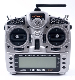
RC System Selection explains how to choose an RC system. Other related topics include:
- Radio/Remote Control Setup - Remote control configuration in QGroundControl.
- Flying 101 - Learn how to fly with a remote control.
- FrSky Telemetry - Set up the RC transmitter to receive telemetry/status updates from PX4.
# GCS Joystick Controller {#joystick}
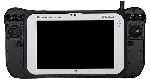
A computer joystick connected through QGroundControl can also be used to manually control PX4 (QGC converts joystick movements into MAVLink messages that are sent over the telemetry link). This approach is used by ground control units that have an integrated ground control station, like the UAVComponents MicroNav shown below. Joysticks are also commonly used to fly the vehicle in simulation.
# Safety Switch {#safety_switch}
It is common for vehicles to have a safety switch that must be engaged before the vehicle can be armed (when armed, motors are powered and propellers can turn). Commonly the safety switch is integrated into a GPS unit, but it may also be a separate physical component.
Note A vehicle that is armed is potentially dangerous. The safety switch is an additional mechanism that prevents arming from happening by accident.
# Data/Telemetry Radios
Data/Telemetry Radios can provide a wireless MAVLink connection between a ground control station like QGroundControl and a vehicle running PX4. This makes it possible to tune parameters while a vehicle is in flight, inspect telemetry in real-time, change a mission on the fly, etc.
# Offboard/Companion Computer
PX4 can be controlled from a separate on-vehicle companion computer via a serial cable or wifi. The companion computer will usually communicate using a MAVLink API like the MAVSDK or MAVROS.
Note Using a Robotics API requires software development skills, and is outside the scope of this guide.
- Off-board Mode - Flight mode for offboard control of PX4 from a GCS or companion computer.
- Robotics APIs (PX4 Developer Guide)
# SD Cards (Removable Memory) {#sd_cards}
PX4 uses SD memory cards for storing flight logs, and they are also required in order to use UAVCAN peripherals and fly missions.
By default, if no SD card is present PX4 will play the format failed (2-beep) tune twice during boot (and none of the above features will be available).
Tip The maximum supported SD card size on Pixhawk boards is 32GB. The SanDisk Extreme U3 32GB is highly recommended (Developer Guide).
SD cards are never-the-less optional. Flight controllers that do not include an SD Card slot may:
- Disable notification beeps are disabled using the parameter CBRK_BUZZER.
- Stream logs to another component (companion).
- Store missions in RAM/FLASH.
# Arming and Disarming {#arming}
Vehicles may have moving parts, some of which are potentially dangerous when powered (in particular motors and propellers)!
To reduce the chance of accidents:
- PX4 vehicles are disarmed (unpowered) when not in use, and must be explicitly armed before taking off.
- Some vehicles additionally require a safety switch be disengaged before arming can succeed.
- Arming is prevented if the vehicle is not in a "healthy" state.
- Arming is prevented if a VTOL vehicle is in fixed-wing mode (by default).
- A vehicle will also usually revert to the disarmed state after landing or if a pilot does not take off quickly enough.
Arming is triggered by default (Mode 2 transmitters) by holding the RC throttle/yaw stick on the bottom right for one second (to disarm, hold stick on bottom left). It is also possible to configure PX4 to arm using an RC button on the RC control (and arming commands can be sent from a ground station).
A detailed overview of arming and disarming configuration can be found here: Prearm, Arm, Disarm Configuration.
# Flight Modes {#flight_modes}
Flight modes provide different types/levels of vehicle automation and autopilot assistance to the user (pilot). Autonomous modes are fully controlled by the autopilot, and require no pilot/remote control input. These are used, for example, to automate common tasks like takeoff, returning to the home position, and landing. Other autonomous modes execute pre-programmed missions, follow a GPS beacon, or accept commands from an offboard computer or ground station.
Manual modes are controlled by the user (via the RC control sticks/joystick) with assistance from the autopilot. Different manual modes enable different flight characteristics - for example, some modes enable acrobatic tricks, while others are impossible to flip and will hold position/course against wind.
Tip Not all flight modes are available on all vehicle types, and some modes can only be used when specific conditions have been met (e.g. many modes require a global position estimate).
An overview of the available flight modes can be found here. Instructions for how to set up your remote control switches to turn on different flight modes is provided in Flight Mode Configuration.
# Safety Settings (Failsafe) {#safety}
PX4 has configurable failsafe systems to protect and recover your vehicle if something goes wrong! These allow you to specify areas and conditions under which you can safely fly, and the action that will be performed if a failsafe is triggered (for example, landing, holding position, or returning to a specified point).
Note You can only specify the action for the first failsafe event. Once a failsafe occurs the system will enter special handling code, such that subsequent failsafe triggers are managed by separate system level and vehicle specific code.
The main failsafe areas are listed below:
- Low Battery
- Remote Control (RC) Loss
- Position Loss (global position estimate quality is too low).
- Offboard Loss (e.g. lose connection to companion computer)
- Data Link Loss (e.g. lose telemetry connection to GCS).
- Geofence Breach (restrict vehicle to flight within a virtual cylinder).
- Mission Failsafe (prevent a previous mission being run at a new takeoff location).
- Traffic avoidance (triggered by transponder data from e.g. ADSB transponders).
For more information see: Safety (Basic Configuration).
# Heading and Directions
All the vehicles, boats and aircraft have a heading direction or an orientation based on their forward motion.

It is important to know the vehicle heading direction in order to align the autopilot with the vehicle vector of movement. Multicopters have a heading even when they are symmetrical from all sides! Usually manufacturers use a colored props or colored arms to indicate the heading.

In our illustrations we will use red coloring for the front propellers of multicopter to show heading.
You can read in depth about heading in Flight Controller Orientation